Sure Power Battery Isolator Wiring Diagram Cadician's Blog
To choose the proper battery isolator for your application the vehicle alternator type is very critical, so verify the alternator you have. Contact Sure Power Industries technical support 503-692-5360 to help verify your alternator/isolator application. The make and model number of alternator is required.

Battery Isolator Wiring Schematic Free Wiring Diagram
A battery isolator schematic is a diagram that illustrates how a battery isolator is connected to the electrical system. It shows the different components and their connections, providing a visual representation of how the system works. Understanding the basics of a battery isolator schematic is important for anyone who wants to install or.
Sure Power Battery Isolator Wiring Diagram Wiring Diagram
For all product, installation or service questions please call ProMariner direct at: 1-800-824-0524 Eastern Time 9:00am - 5:00pm. ProMariner Marine Battery Isolators are rated for use with negative ground alternators that range from 10 amps to 130 amps output, and will operate on 6, 12, 24, 32, 36 volt negative ground systems.
12V Battery Isolator Wiring Diagram Sure Power Battery Isolator Sure
The diagrams below are intended as an overview and some details are missing from them. The Diode Battery Isolator The diode type battery isolator uses semiconductor diodes to split the current from the alternator or generator and charge 2 or more batteries at the same time.

Understanding A Dual Battery Isolator Wiring Diagram Moo Wiring
Step by step Battery Isolator install (12V 140 Amp Dual Battery Isolator by KeyLine Chargers - Voltage Sensitive Relay (VSR) Pro Dual Battery Kit). This isol.
Canadian Energy™ Battery Isolator 101 Youtube Battery Isolator
An overview of how to wire a Stinger isolator to run dual batteries in a truck, van, or car. The isolator keeps the main battery from going dead. 200 amp St.

How To Install A Battery Isolator In Your Conversion Van Parked In
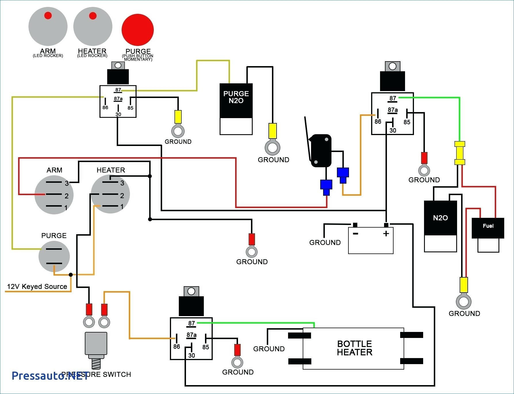
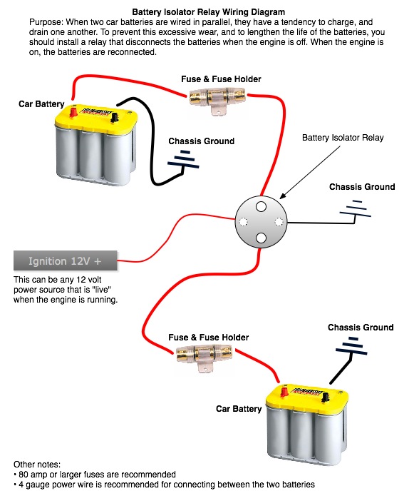
Wiring Diagram Wiring the relay: 1. The black wire coiled inside the relay needs terminated to a good ground location using the included blue crimp connector. This wire is simply used as a ground for activating the relay. 2. One terminal on the relay should be connected to the positive terminal of the primary starting battery using 6ga red wire.
battery changeover switch diagram Wiring Diagram and Schematics
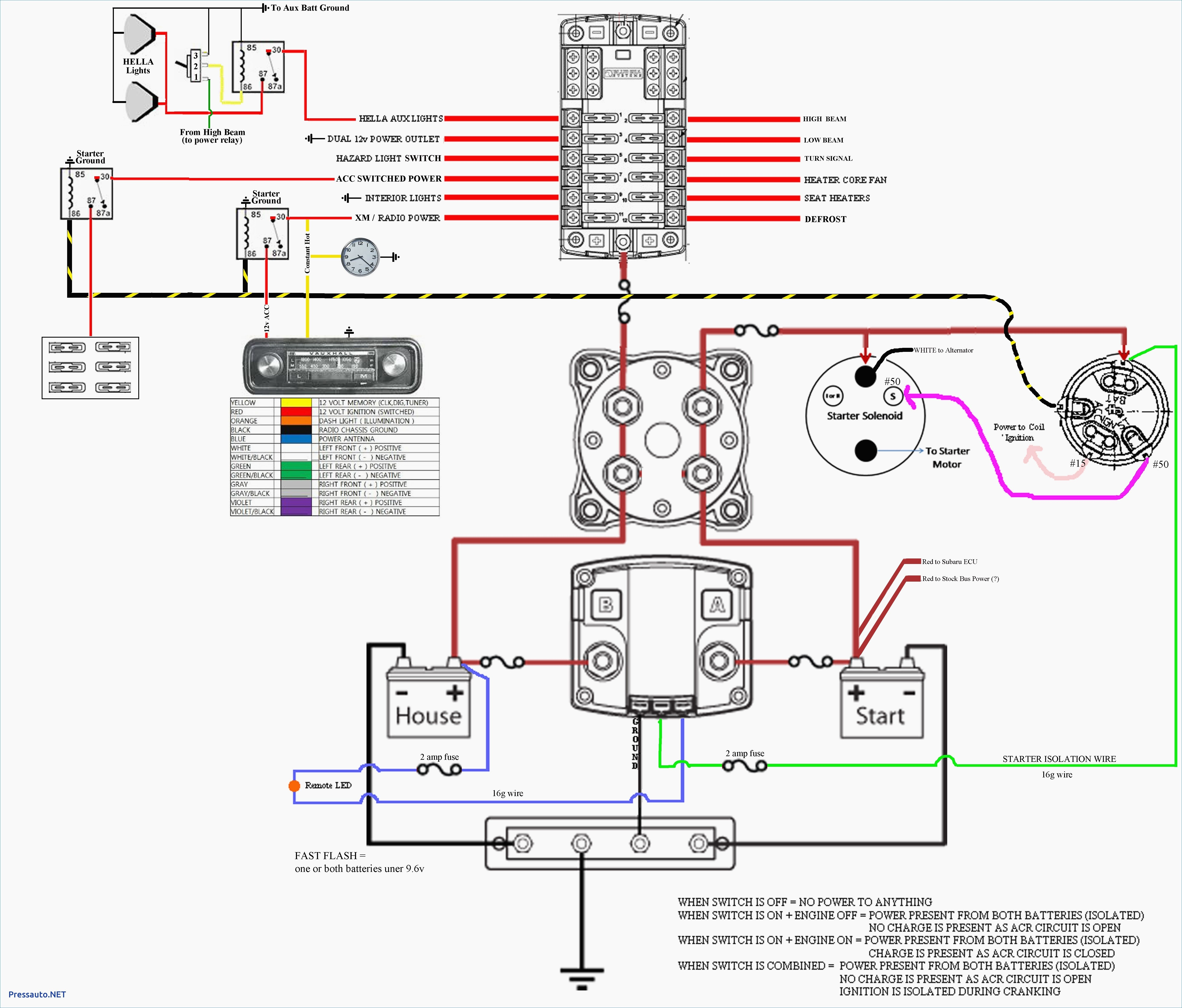
The wiring diagram for a dual battery isolator switch typically includes several key components. First, there is the switch itself, which is used to manually connect or disconnect the batteries. This switch is often placed in a convenient location, such as the dashboard or near the batteries themselves, for easy access..

Multi Battery Isolator Wiring Diagram Free Wiring Diagram
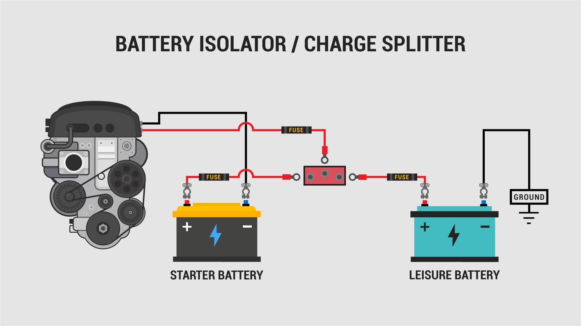
Battery isolators make sure that extra batteries in a dual or multiple battery system are charged properly. They also prevent extra devices in the vehicle from completely draining the main battery. When the alternator is charging the main battery, the isolator will allow current to also flow to the auxiliary battery.
Essay Guides Top Features of Battery power Isolator in your Vehicles
How To Install a Battery Isolator (EASY & CHEAP!) - YouTube 0:00 / 8:10 Is your battery going flat or you need to store your car without draining the battery? In this super simple DIY.

Battery Isolator Wiring Schematic Free Wiring Diagram
What You'll Need Whether it is a fuel line replacement or wiring a battery isolator, you can accomplish many seemingly tough jobs on your own. If you find yourself in need of a battery isolator wiring, here are a few tools and materials needed, as well as steps that can help to guide you. Step 1 - Turn Everything Off and Prepare

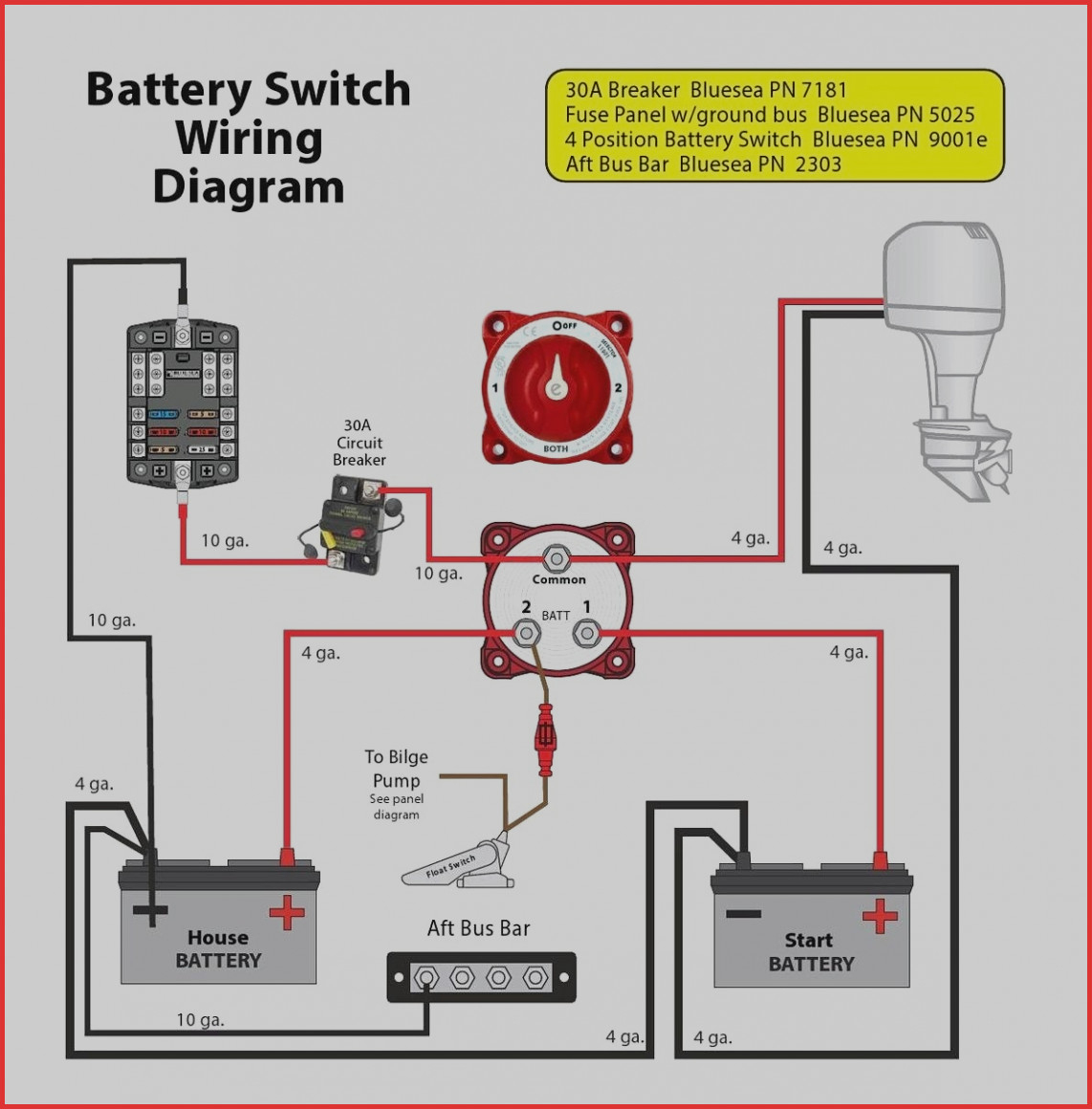
Boat Battery Isolator Wiring Diagram
Note: The battery isolator is supplied with a set of wiring hardware. If the hardware packet is lost or missing from the packaging, contact the factory. Using incorrectly sized hardware on the wiring studs will damage the isolator. Stud sizes are as follows: 70 amp models — 6 mm (1.0 pitch) 120 and 165 amp models — 8 mm (1.25 pitch) 1.
Noco Battery Isolator Wiring Diagram
Installation Instructions Smart Battery Isolators Part Numbers: 48525 and 48530 Power Studs: Wire Connections: Mounting: 5/16" -24 copper studs Active High, 250mA Violet: BOOST Black: GROUND White: STATUS 5/16"x19/32" on 2 13/64" centers 7.9 x 15.1 on 56 mm centers Dimensions: Operating Temperature Range: 3.4" x 3.4" x 3.1" -40 to +85 °C
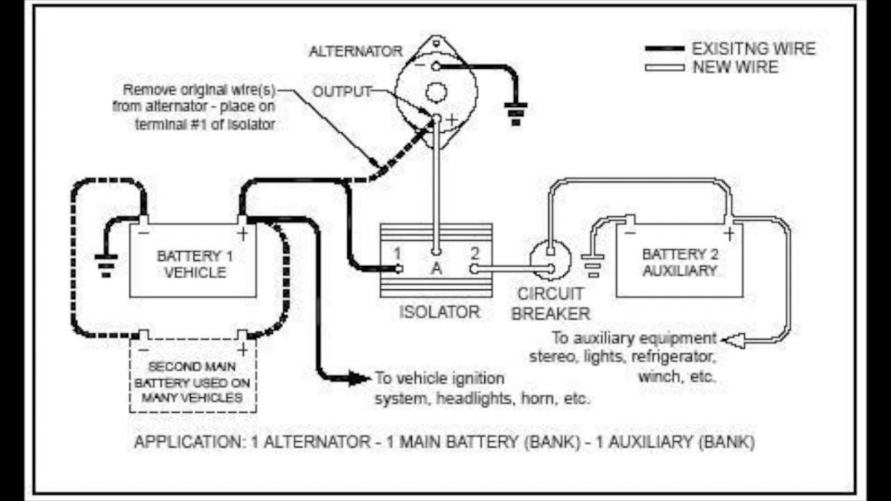
How to Wire Up a Sure Power 120 Amp Two Battery Isolator
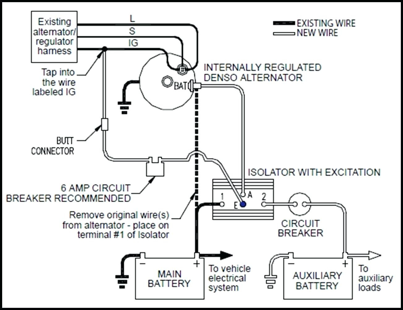
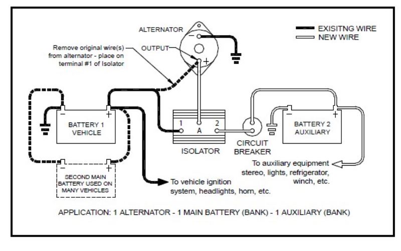
Wiring diagram for Battery Isolator Question: Not sure what post 1-2-A-and E go to asked by: Mike Helpful Expert Reply: For your battery isolator similar to # DW08771, you will have connection posts for each battery and for an alternator. The main battery will connect to position one and the alternator to the A post.
Battery isolator relay cole hersee doorreka
Link the wires to the isolator. Shred a section of the red cable's end, then curb the end using a ring terminal. Subsequently, place a blue insulated ring terminal on the black cable's end, connecting to the isolator. Don't forget to crimp the connections. Afterward, you'll find bolts along the isolator's underside.
Sure Power Battery Isolator Wiring Diagram Cadician's Blog
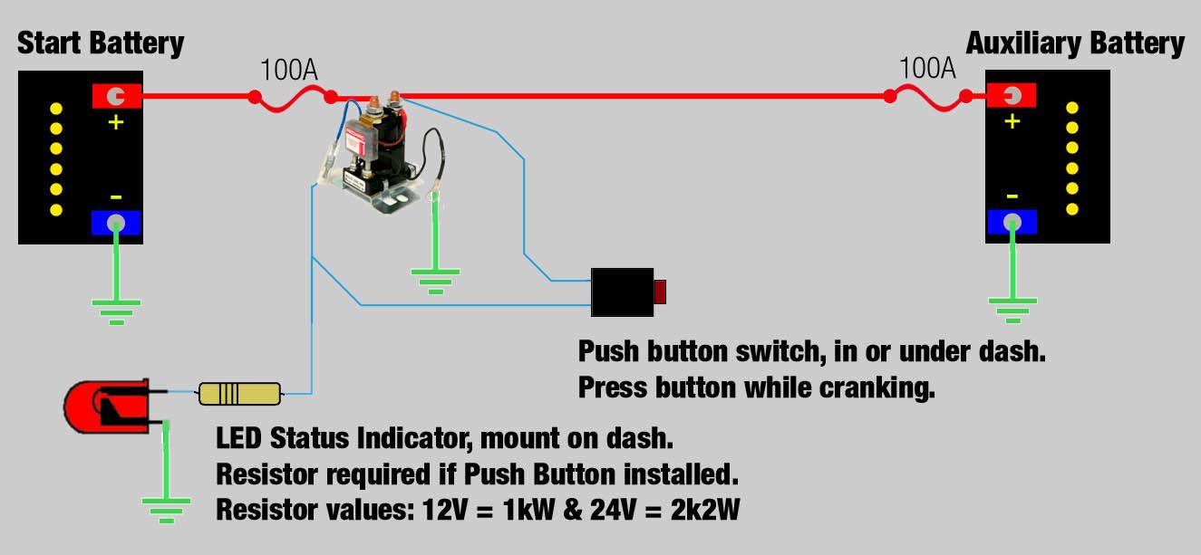
Wiring Diagram : Feature Dual battery sensing Fully automatic Easy 3 wire connection at the battery. No need to bypass existing alternator wiring Ignition protected Manual Remote Model Summary The battery isolator allows two batteries to be charged at the same time.
