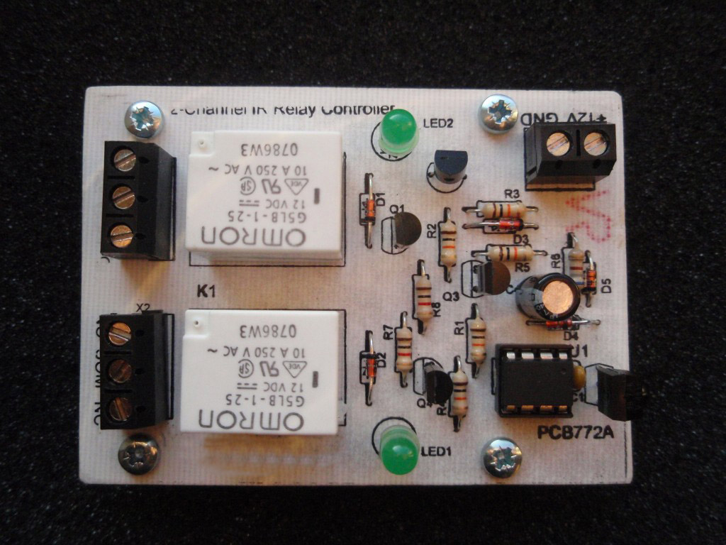
2Channel IR Relay Controller
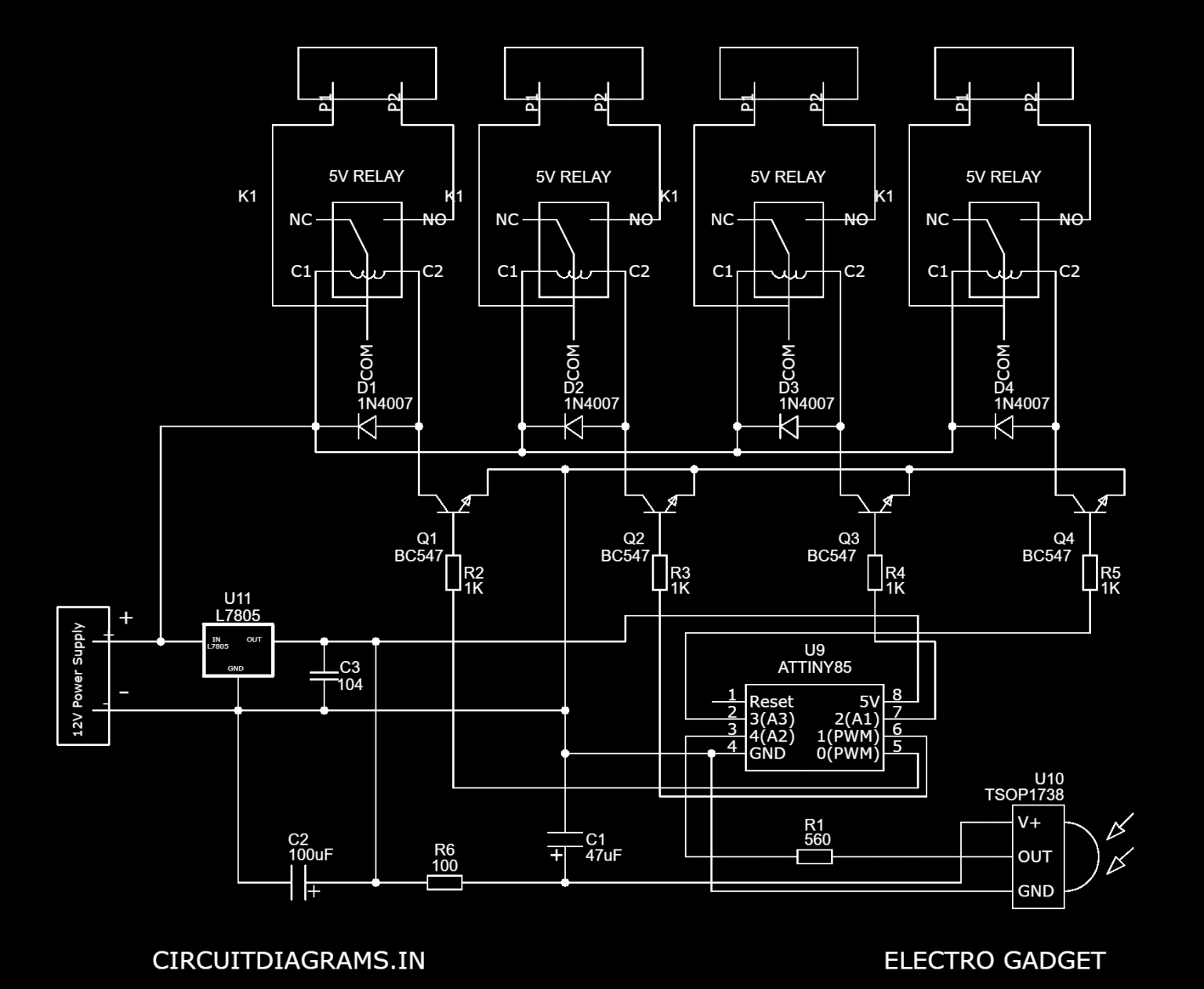
ATtiny85 IR Remote Control Circuit Diagram: Connect the voltage and GND pins of the IR sensor to the 5V and GND pins. Connect the S pin of the IR Sensor to the ATtiny85 Pin 5. To avoid an confusion make sure you study the ATtiny85 Pinout diagrams given above.

4Channel IR Remote Control System Using ATtiny85
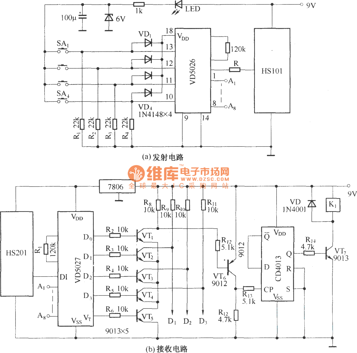
4 Channel Infrared (IR) Remote is a simple project using the popular HT12A and HT12D encoder / decoder chips from Holtek. Specifications Supply - Transmitter: 2.4 ~ 5 VDC, 5 V @ 20 mA & Receiver: 5 ~ 6 VDC, 5 V @ 50 mA Output - 4 Latched/Momentary TTL compatible outputs Crystal based oscillator for reliability of operation
4Channel IR Remote Control System Using ATtiny85
Features. Supply - Transmitter : 3 to 5 VDC, 5 V @ 20 mA & Receiver : 5 VDC @ 200 mA. Output : 4 channel Latch or Momentary on board Jumper for selection. Crystal based oscillator for reliability of operation. Jumper selectable 8 bit address code. LED output to indicate reception. On/Off slide switch in the transmitter.
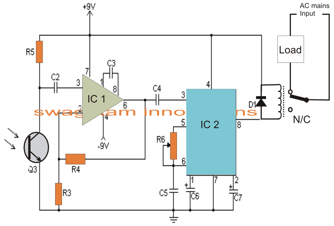
Remote Control Circuit Through RF Without Microcontroller The Circuit
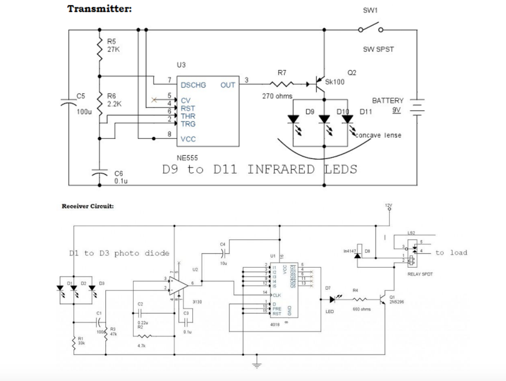
Circuit Diagram Video Demonstration Parts List The following parts will be required for making the above explained infra red remote control circuit: R1 = 100 ohms, R3 = 1K, R2 = 100K, R4, R5 = 10K, C1, C2, C4 = 10uF/25V C6 = 100uF/25V C3 = 0.1uF, CERAMIC, C5 = 1000uF/25V,
4 Channel Infrared Remote Module ElectronicsLab
The TSOP1838 is an infrared sensor module that can receive signals from an infrared remote control. It operates at a carrier frequency of 38kHz, which is commonly used by most remote controls. The TSOP1838 not only detects infrared signals but also decodes them, allowing you to use different codes for different functions.

4Channel IR Remote Control System Using ATtiny85
4017 ic projects + TSOP Infrared IR REMOTE CONTROL 4 channel ( 3 ON & 1 OFF )Ide ini datang ketika saya harus bolak balik dalam menyalakan dan mematikan kip.
4 Channel Ir Remote Control Circuit For Home Appliances Home Rulend
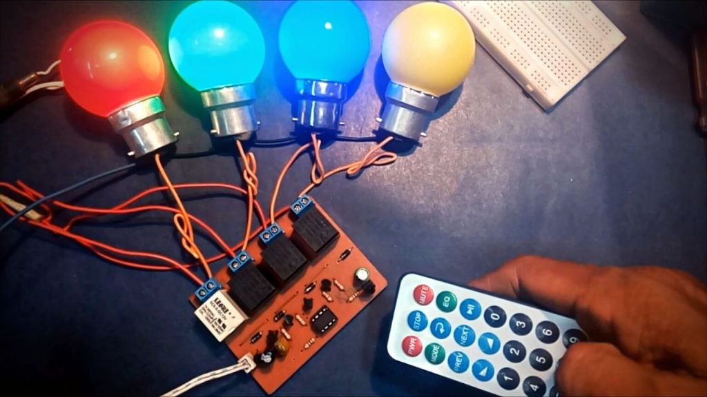
Step 1: Story: The previous month, I made an Electric board relay-controlled circuit. Using the exact schematics and circuit diagram, I want to build an IR controlled Electric extension board. Keeping the form factor in mind, I designed a PCB and ordered it from JLCPCB.

4 Channel IR Remote Control Pioneer Electronic Store
Using the exact schematics and circuit diagram, I want to build an IR controlled Electric extension board. Keeping the form factor in mind, I designed a PCB and ordered it from JLCPCB. And JLCPCB is the sponsor of this project; PCB manufacturing service is just available for $2. Features: 4 channel controller IR remote compatible Range <50 meter
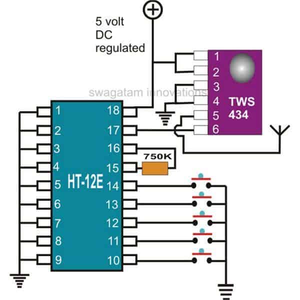
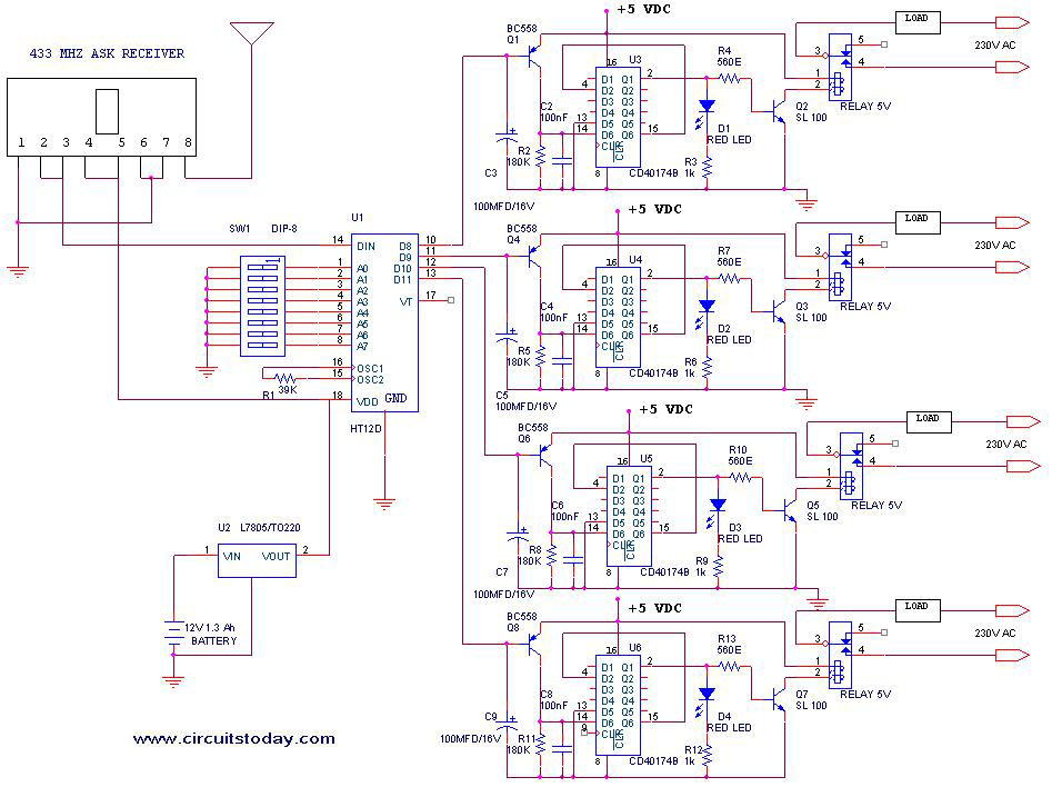
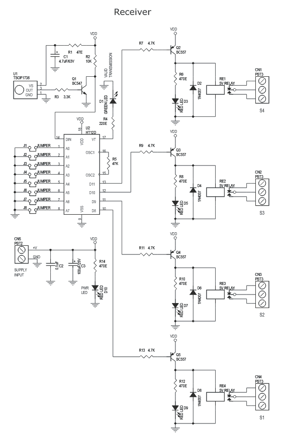
RF Remote Control Circuit using 433MHz and 315MHZ RF Modules
PT2262 is a remote control encoder paired with PT2272 utilizing CMOS technology. Its encode data and address pins into a serial coded waveform suitable for RF modulation. Circuit uses 8 bits of tri-state address pins providing up to 6561 address codes, thereby, drastically reducing any code collision and unauthorized code scanning possibilities.
4 Channel Infra Red Remote Controller using HT12A & HT12D and 4 Relay (3)
IR Remote Control Switch Circuit Diagram In above IR Remote Control Light Switch, Output of TSOP1738 oscillates at the rate of 38KHz, which is applied to clock pulse of 4017. So we have connected a 1uF capacitor across the output of the TSOP so that this 38KHz pulse train is counted as one clock pulse to the IC 4017.
Draw your wiring Ir Transmitter And Receiver Circuit Diagram Pdf
️ Hi Friends :) ️ Today Video Topic About _ For You How To Make A 4 Channel Ir Remote Control System Using Arduino Uno _||#irremote#irreciver#automation#ard.
%2Bcopy.png)
Electronic's Lovers Technology We Love
4-Channel IR Remote Control System Circuit Diagram Components Required Arduino Board (Any) ATtiny85 Microcontroller TSOP1738 Infrared Sensor 7805 Voltage Regulator 5V Relay Module (x4) BC547 NPN Transistor (x4) 1N4007 PN Diode (x4) Resistor (1K, 560, 100) Polar Capacitor (100uF/25V, 47uF/25V) 0.1uF Ceramic Capacitor
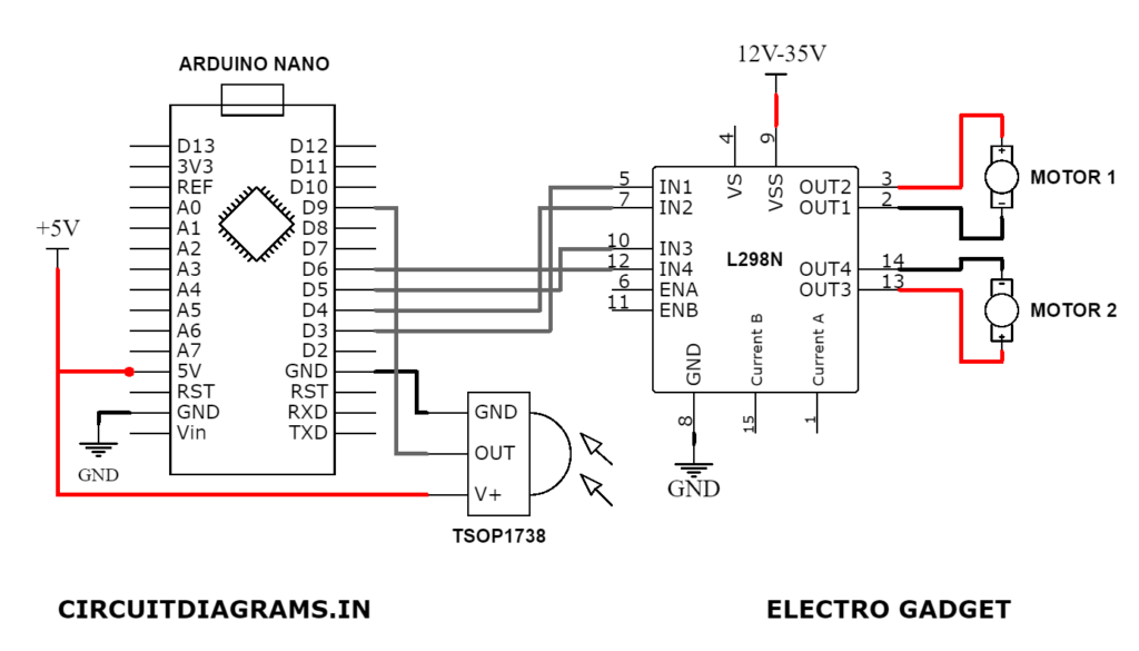
IR Remote Control Car Using Arduino and TSOP1738 Sensor
Im a student major in science physic. Im a third year student, so I have to do a final year project. My title is building a Remote control by using Infrared. I have no ideal how to do the circuit which can on 4 LED in different time by using 4 buttons remote control. I know how to do single channel on off, but come to 4 channel I face difficulty.
4Channel IR Remote Control System Using ATtiny85
Figure 1 - Schematic of the simple 4-channel ON-OFF remote control with ATtiny13(A)(V). Figure 2 - Schematic of the relay power swith. Build it 4 times when using all 4 channels. Figure 3. - IR transmitter signal waveforms. Transmitter configuration and security bits setting. (Hexadecimal values are Low Fuse: 6A, High Fuse: FF.)
10+ 4 Channel Remote Control Circuit Diagram Robhosking Diagram
How to Make # IR 4 Channel Remote Control System for your Room Appliances (Very Easiest Way) Et Discover 361K subscribers Subscribe 257K views 3 years ago JLCPCB Prototype for $2 (Any.
How To Draw Control Circuit Diagram Wiring Diagram
Here it is the circuit diagram which we can build it with the help of this diagram. This diagram is available on google images i just saved it and make my own ir chip with this diagram. Components:-. IC: cd4017 with base and TSOP 1738 (ir receiver) Resistors: 4.7k x 2, 1k, 100 ohms,100k. Transistors: bc557 and bc547.